Retargeting Images Using Parallax
I came up with a neat way to retarget images using a mesh that is transformed by rotating and doing an ortographic (non-perspective) projection. This is generally quite interesting since it can be done using a mesh and simple transformations and so can be done almost completely on the GPU. Even using a mesh can be avoided if one uses a height map à la parallax mapping to alter the texture coordinates so just one quad needs to be drawn (with a suitable fragment shader, of course).
The idea is simply to have areas of images at a slope depending of how much the areas should be resized when retargeting. The slope angle depends of from what angle the source image is viewed to get the retargeting effect since the idea is to eliminate the viewing angle using the slope.
Here’s a more detailed explanation:
-
Create an energy map of the source image, areas of interest have high energy
-
Traverse the energy map horizontally accumulating the energy value of the current pixel and the accumulated sum from the previous pixel
-
Repeat the previous step vertically using the accumulated map from the previous step. The accumulated energy map now “grows” from the upper left corner to the lower right corner. You may need a lot of precision for the map
-
Create a mesh with the x and y coordinates of each vertex encoding the coordinates of the source image (and thus also the texture coordinates) and the z coordinate encoding the accumulated energy. The idea is to have all areas of interest at a steep slope and other areas with little or no slope
-
Draw the mesh with ortographic projection, using depth testing and textured with the source image
-
Rotate the mesh around the Y axis to retarget image horizontally and around the X axis to retarget image vertically
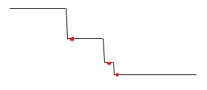
Here is a one-dimensional example (sorry for the awful images):
The red dots represent areas of interest, such as sharp edges that we don’t want to resize as much as we want to resize the areas between the details. We then elevate our line for every red dot:
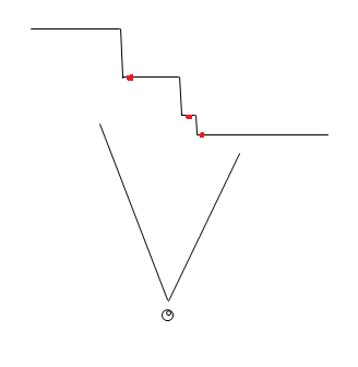
Imagine the above example as something you would do for every row and column of a two-dimensional image. Now, when the viewer views the mesh (which is drawn without perspective) he or she sees the original image:
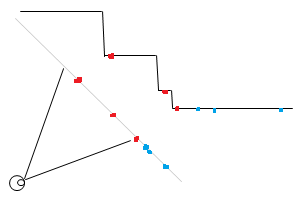
However, if the viewing angle is changed, the red dots don’t move in relation to each other as much as the areas that are not elevated when they are projected on the view plane. Consider the below example:
Note how the unelevated line segments will seem shorter from the viewer’s perspective while the distance between the red dots is closer to the original distance. The blue dots in the above image show how areas that have little energy and so are not on a slope, thus will be move more compared to the red dots.


